Rover Projects
Autonomous (Self-Driving) Rover - Quarter 2
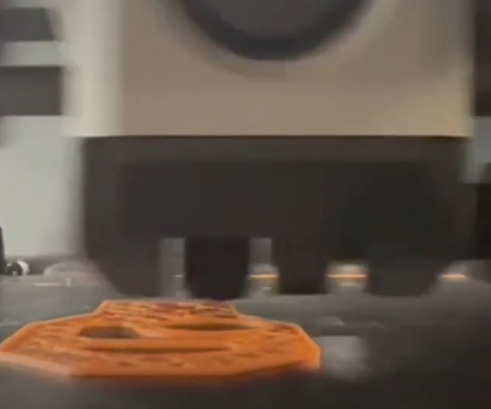
Objective: Create a line-following rover that could complete a course and grab a red can at the end of the course.
$300 budget and a time constraint of ten weeks
Top ten fastest rovers to complete the preliminary track would move on to the final course.
-
My designated role was team leader for this quarter once again, managing our team’s tasks for this project. I was also responsible for the Arduino programming and troubleshooting of the rover!
-
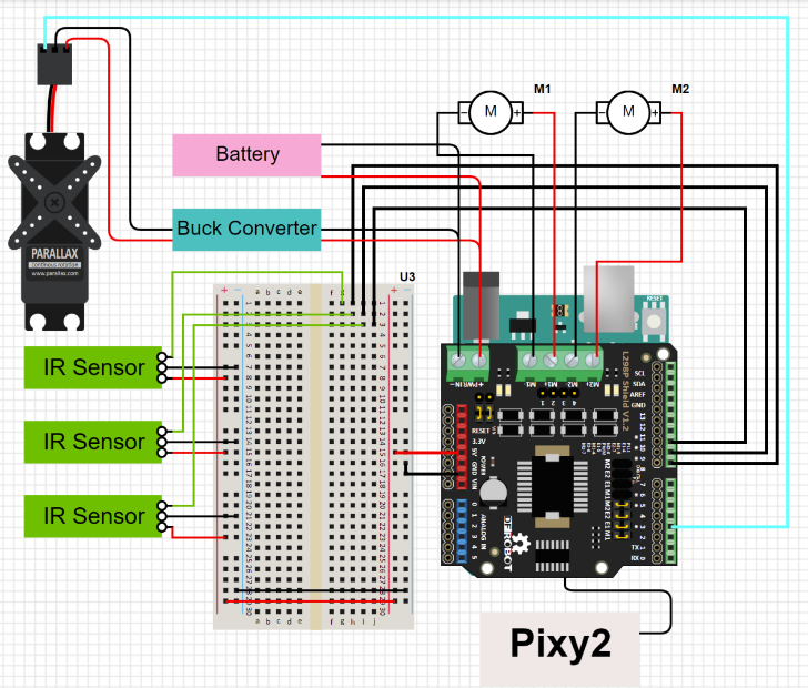
Our coding structure contains different stages in the loop to signify what stage of the algorithm our rover is currently in line following, object tracking, or claw mechanism.
Slots for battery straps, claw, wires, castor wheels, standoffs, and Arduino were made
Claw mechanism: parts did not assemble correctly and claw would close unintentionally, leading to modified code and more drilling to fix it.
-
Our rover completed the track with the fastest time, winning us first place in the competition! Even though we won the competition, we still could have made some improvements to improve the rover. The chassis of our rover was durable enough to withstand the track itself as the track was relatively flat. However, a different material for the chassis would have shaved off a few grams from our rover and in theory, lower the amount of time to complete a lap.
Our team celebrated the win with Yogurtland!
ROR (Remote-Operated Rover) - Quarter 1
Objective: Create a remote-controlled rover over ten weeks that could navigate a race course.
Rover budget of $250 without 3-D printing or a budget of $275 with printing.
The rover must be able to operate for at least 10 minutes without replenishing/recharging its energy source.
-
Through this remote-controlled and autonomous rover building program, I have gained experience in MATLAB, Arduino, and Solidworks CAD Software.
As Team Leader, I had the responsibility of coordinating weekly meetings, organizing deadlines/roles, and assisting with fabrication, coding, and electronic experience.
-
During fabrication, some of the chassis was adjusted in order in accordance with issues found in testing. For example, the slot of the steering was widened to allow a larger steering angle. Another modification was the hole cut out of our chassis to allow for the servo to sit more securely with our chassis. The CAD model does not account for the diameter of a shaft collar, but in fabrication, the diameter of the hole on the back axle support matches a shaft collar’s.
Steering SystemThe steering mechanism is made up of 7 individual parts, only 5 of which were kept in the final rover.
There are two “legs” connected by a lower-beam with a pole and an upper-beam that is mounted onto the chassis itself.
In the completed rover, the 3D-printed pins that served as hinges attaching the legs and lower-beam were swapped for 2-inch shafts attached via shaft-collars.
-
The durability of the rover improved over time. We increased infill on our steering system and replaced the plastic caps, holding the steering together, with shaft collars. After those revisions, when the rover was tested again it was very durable and can withstand the course without any damage.
Here is the written Arduino code from the Autonomous Rover project, along with additional photos from my work below.